Source: Roblox Creator Hub · CC BY 4.0 · View source · Code samples: MIT Imported 2026-10-03. Formatting adapted for this site.
Beams
A Beam is an object that renders a Texture between two Attachment objects. By setting beam properties, you can:
- Add a texture and color gradient to create interesting visuals like waterfalls and force fields.
- Modify a beam's transparency so that it fades over time.
- Warp its shape by changing the width or curve of each attachment point.
- Specify the texture's length and mode to affect how it repeats across the beam's length.
Create beams
Before you begin to create a beam, it's useful to toggle on visibility of attachments so you can see where the beam starts and ends. You can do so by enabling Show Constraint Details from Studio's View menu.
To create a beam:
Create two parts and position them a short distance from each other. One will act as the start of the beam and the other as the end of the beam. Group the parts into a
Model.In the Explorer window, add an
Attachmentobject to each part:- Hover over one part and click the ⊕ button. A contextual menu displays.
- From the contextual menu, insert an Attachment.
- Repeat for the other part.
In the Explorer window, add a
Beamobject to the model:Hover over the model and click the ⊕ button. A contextual menu displays.
From the contextual menu, insert a Beam.

Select the new Beam object and assign its attachments. Ensure you assign each attachment property to a different
Attachmentobject.- In the Properties window, select the Attachment0 property. Your cursor changes.
- In the Explorer window, select the attachment of the part you want to be the start of your beam.
- Back in the Properties window, select the Attachment1 property. Your cursor changes.
- In the Explorer window, select the attachment of the part you want to be the end of your beam.
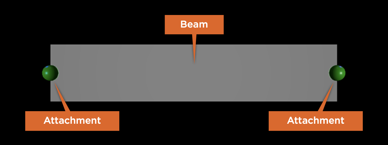
Default beam between two attachments
Note
Beams require attachments to function properly. If you remove either attachment object from step 4, the beam stops rendering its texture.
Customize beams
By experimenting with the following properties, you can customize a beam's visual appearance to make unique gameplay elements like force fields, waterfalls, and pathway obstacles.
Note
The visual quality of your beams can change depending on the graphics settings on the player's device. To review your beam across quality levels, it's recommended to open Studio Settings, search for Editor Quality Level, and set it to the both the lowest and highest level after you finish customizing your beam.
Texture
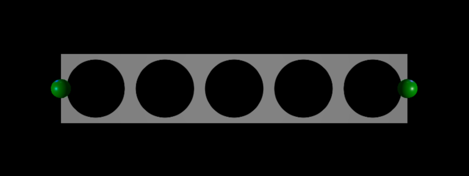
The Texture property renders that texture across the length of the beam. You can set a beam's Texture property to any asset ID. For more information, including how to add or upload your own textures, see here.
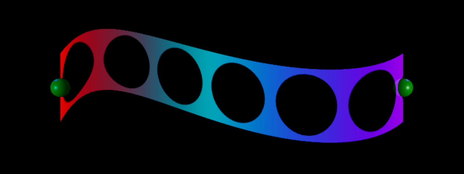
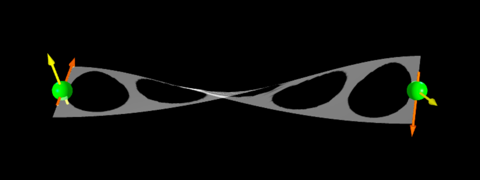
A beam renders its texture using two triangles drawn between Segments, and the segments are laid out between the two attachment points' orientation. When you rotate attachment points in different directions, segments also rotate.
Color
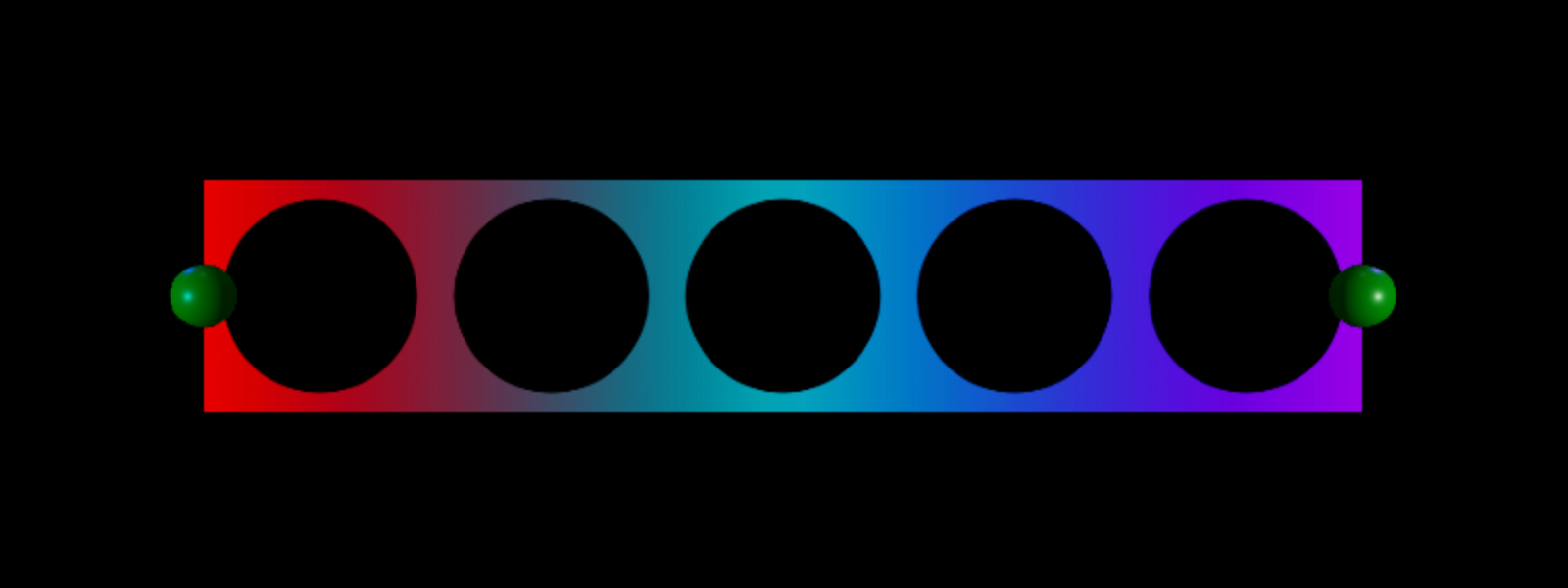
The Color property tints the beam's texture to either a specific hue, or to a gradient ColorSequence across its entire span.
Constant Color
In the Explorer window, select the beam.
In the Properties window, select the Color property. You can either:
- Click on the color square to open the Colors pop-up window and select a color.
- Input three numbers into the RGB color value field.

Color Gradient
In the Explorer window, select the beam.
In the Properties window, click inside the Color property field, then click the ⋯ button.

In the color sequence popup, each triangle on the bottom axis is a keypoint that determines the color value of the beam at that point along its span.
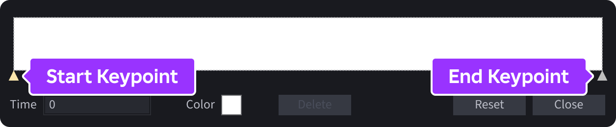
Click the keypoint at the start of the color sequence, click the small square next to Color, and select a color from the popup window.

If you want the beam to change color near the end of its span, click the keypoint at the end of the color sequence, click the small square next to Color, and select a color from the popup window.

For more customization, you can:
- Add another keypoint by clicking anywhere on the graph.
- Make a color change sooner or later within the gradient by dragging an intermediary keypoint to a new position.
- Delete an intermediary keypoint by selecting it and clicking the Delete button.
- Reset the entire sequence by clicking the Reset button.

Transparency
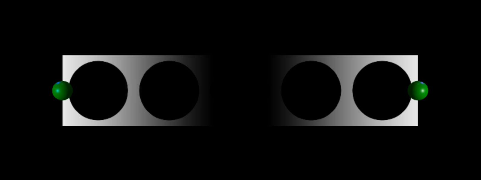
The Transparency property sets the transparency of the beam as a consistent value or as a NumberSequence with ranges from 0 (totally opaque) to 1 (fully clear).
Constant Opacity
- In the Explorer window, select the beam.
- In the Properties window, select the Transparency property.
- Input the desired opacity for the beam.
Number Sequence
In the Explorer window, select the beam.
In the Properties window, click inside the Transparency property field, then click the ⋯ button.

In the number sequence popup, each square at the start and end of the graph is a keypoint that determines the opacity value of the beam at that point along its span. By default, the graph defaults to a straight line and the beam is of consistent opacity.

Perform any of the following actions:
- To change the opacity at a point, click on a keypoint and either drag it up or down, or enter a value in the Value field.
- To insert a new keypoint, click on any point in the graph.
- To delete a keypoint, select it and click the Delete button.
- Reset the entire sequence by clicking the Reset button.

Width
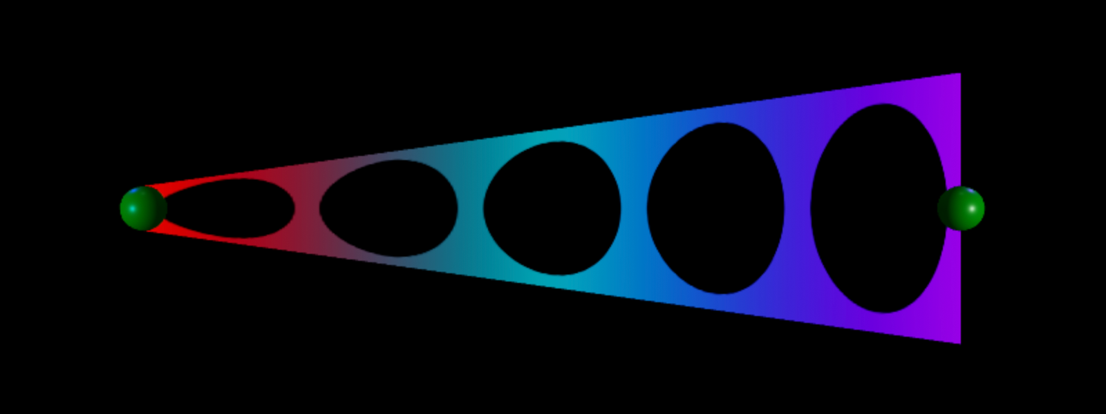
You can set the beam's width in studs at each endpoint by configuring the Width0 and Width1 properties. A higher value equates to a larger width and a lower value equates to a smaller width. If you set either value to smaller than 0, Studio sets it back to 0.
The beam below has a Width0 value of 0.5 and a Width1 value of 3.
Texture length/mode
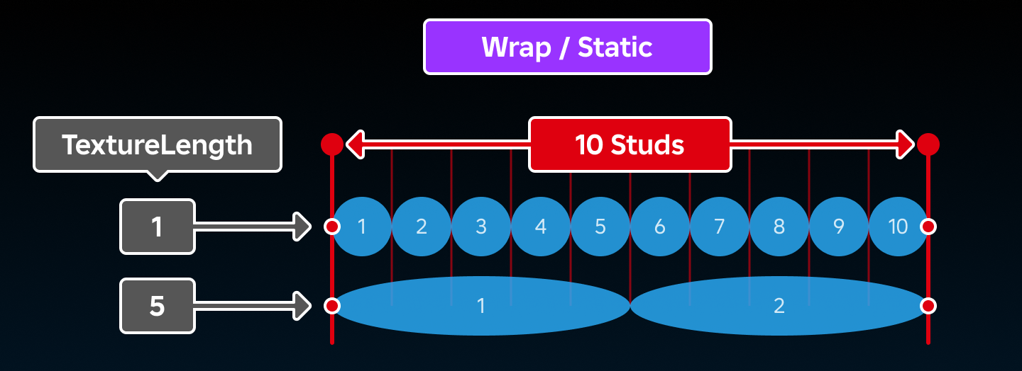
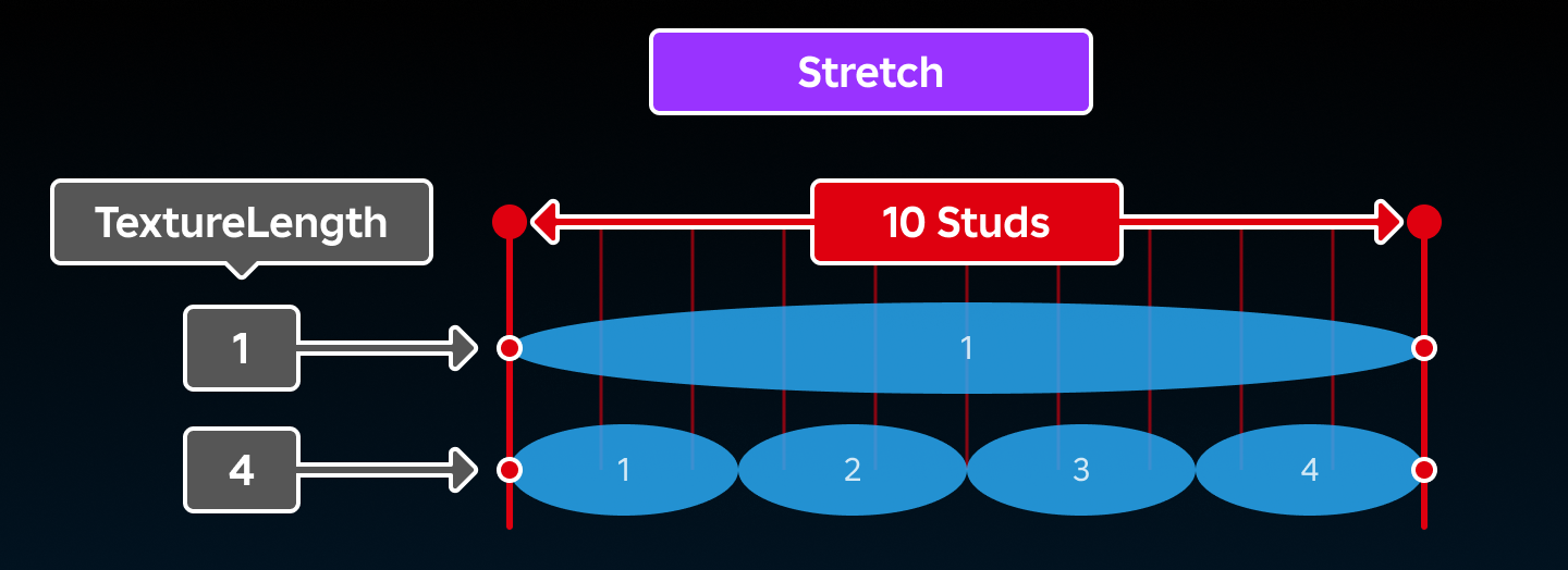
A beam's TextureLength and TextureMode determine how its texture repeats across its length.
When TextureMode is set to TextureMode.Wrap or TextureMode.Static, the texture repetitions will equal the beam's overall length (in studs) divided by its TextureLength.
When TextureMode is set to TextureMode.Stretch, the texture will repeat TextureLength times across the beam's overall length.
Facing
A beam is a 2D projection existing in 3D space, meaning that it may not be visible from every angle. The FaceCamera property, when set to true, ensures that the beam always faces the CurrentCamera, regardless of its orientation.
Default vs. FaceCamera
Curve
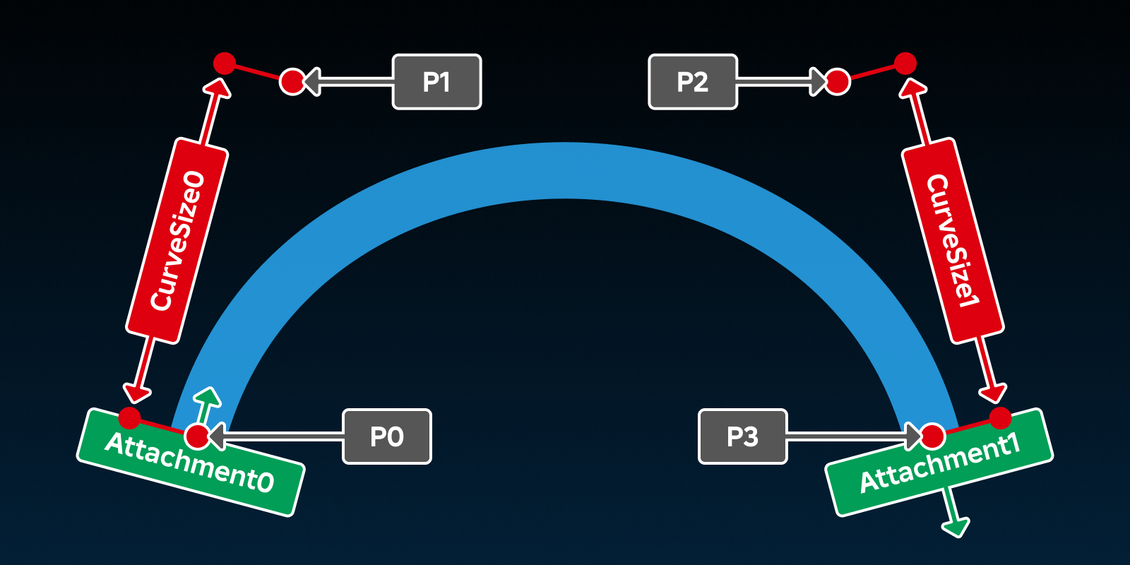
Beams are configured to use a cubic Bézier curve formed by four control points. This means they are not constrained to straight lines and the curve of the beam can be modified by changing CurveSize0, CurveSize1, and the orientation of the beam's Attachments.
- P0 — The start of the beam; position of
Attachment0. - P1 —
CurveSize0studs away fromAttachment0, in the positive X direction ofAttachment0. - P2 —
CurveSize1studs away fromAttachment1, in the negative X direction ofAttachment1. - P3 — The end of the beam; position of
Attachment1.